|
Montana SPX passive to active
How difficult is it really to take the big step from passive to active crossing?
... Here is an example of such a project carried out on a pair of older Montana SPX speakers.
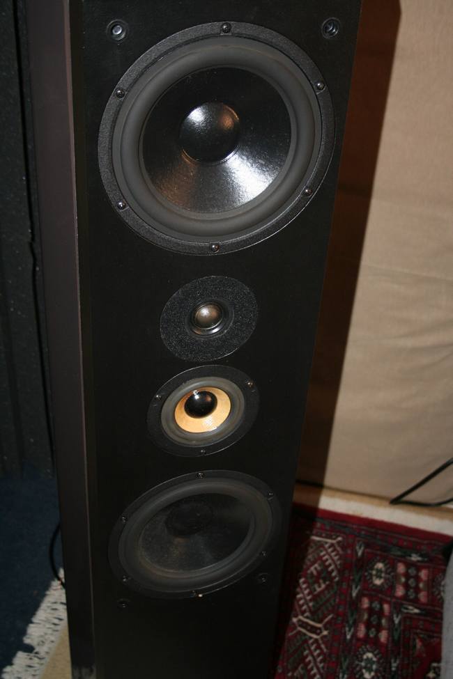
Montana SPX is a 3-way design with dual M22WR-08 woofer drivers from Danish Vifa +
Scan Speak 2905/9700 (I think) + 13M/8636-00. The SPX PDF manual you can find on the net is a
variant with the smaller woofers M18WH-08, but otherwise all information should be the same.
http://www.highend.no/spx.pdf
You can see a thread of this project on the Danish forum Nerds.dk:
Montana SPX passiv til aktiv
I have listened and measured a bit on the passive SPX. The sound is quite reasonable although
I miss some level and precision in the bottom end and detail in the top end. The bass has a
slight boomy peak somewhere below 100Hz and at somewhat stronger SPL the treble quickly gets
very aggressive (distorted). This evaluation is absolutely not absolute, as it is based on a
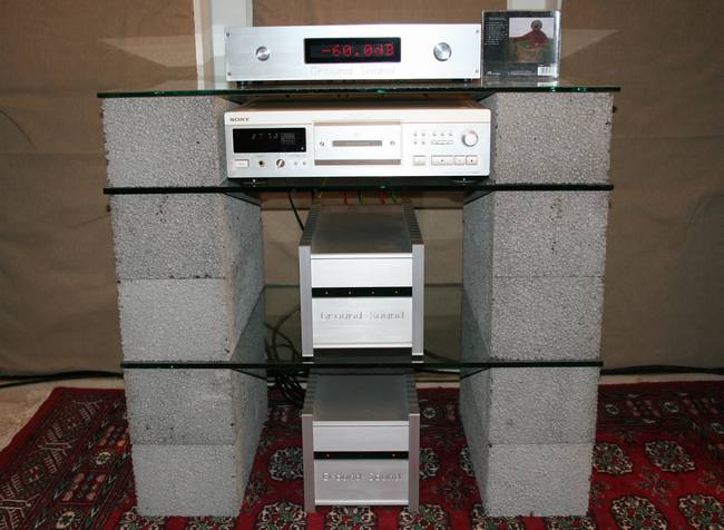
relatively short listening period of an evening + half morning. For this evaluation, the
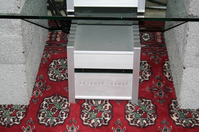
loudspeakers were driven by a Ground Sound H-Amp-XX dual power amplifier consisting of 2 x PA6CC,
PSU12DB and TR1000 - approx. 350W into 8 ohms / 600W into 4 ohms. The same power amplifier will
be powering the bass section in the active version.
Measuring the passive SPX at approximately 90cm distance "in room".
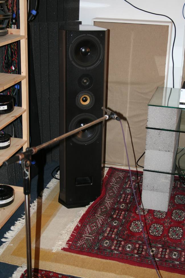
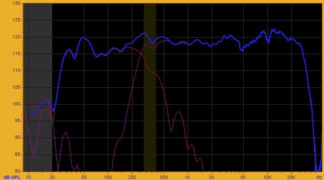
I have measured the total frequency response and bass and treble / midrange separated (bi-wiring).
This gives an impression of the crossing between bass and midrange and it explains the somewhat
uneven response around the crossover point due to the inequality of the flanks. The acoustic slope
of the midrange will later show that this is the course of the slightly bumpy frequency response
and has to be taken into account making a better setup.
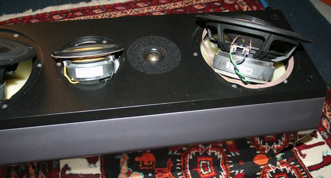
AND NOW - the task of removing the passive crossover:
I decided to remove the passive crossover as gently as possible in order to be able restore SPX'erne
into passive version, since they are borrowed for the purpose and may be sold as passive later.
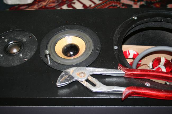
Since the units sat very firmly in the boxes, I used the smart trick by screwing a little too big
self-tapping screw into one of the holes in the driver which made it possible to pull the driver
free from the enclosure. However, this was totally impossible with the treble, so here I had to "settle"
with the original leads to the tweeters and taking care not to burn them during measurements (MLS signals).
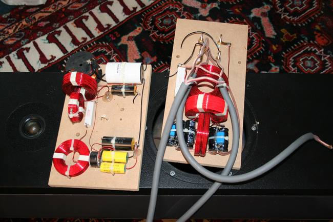
Here it is IMO the "evil" passive crossover immense 5kg per. loudspeaker.
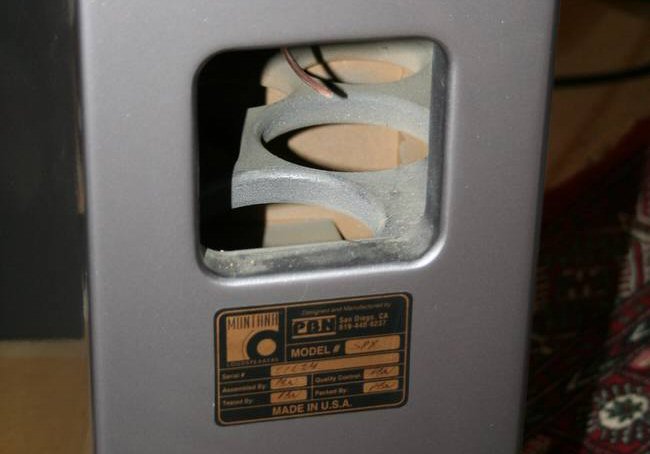
A hole to be filled...
Here is the test "Will the plywood plate with the 8-pin Neutrik Speakon connectors fit?". I may also
inform that the Speakon connectors has low contact resistance and therefore should not be a reason
to opt this type of connector + the plug is very handy when it comes to many conductors into an
active loudspeaker box.
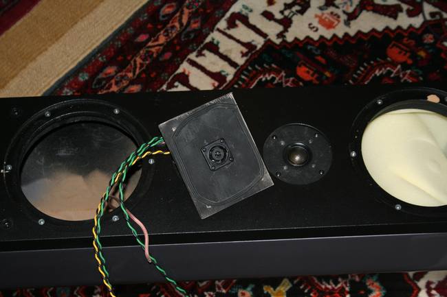
Quick and dirty - quick spray paint of the plywood with 3 x twisted colored wires to avoid interference
between cables for each drivers, while in practice the twisted wires are easier to distinguish.
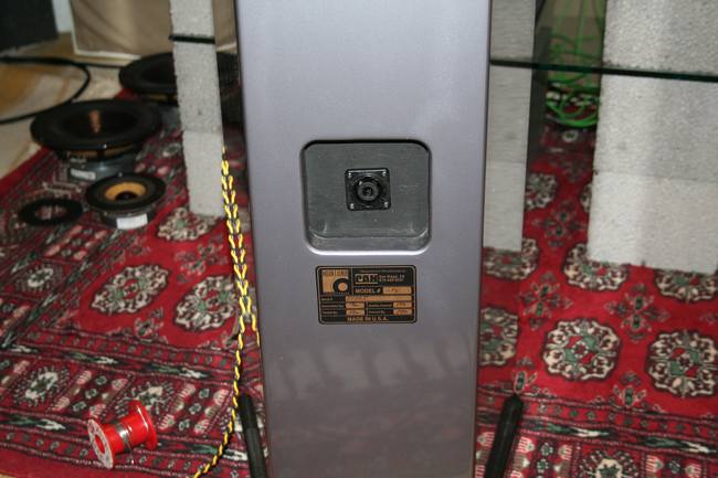
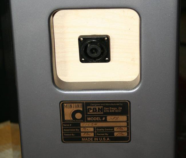
Contact plate is in place and "almost" nicely done - it's just the back of the speaker "and when the
music flows, it is not seen" - you can probably make it nicer...
The entire operation took about 3 hours with various provisioning breaks -  .
You can probably do it an hour faster, but you should of course proceed cautiously to avoid damage
to the cabinets and drivers. .
You can probably do it an hour faster, but you should of course proceed cautiously to avoid damage
to the cabinets and drivers.
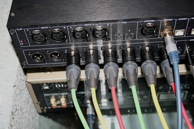
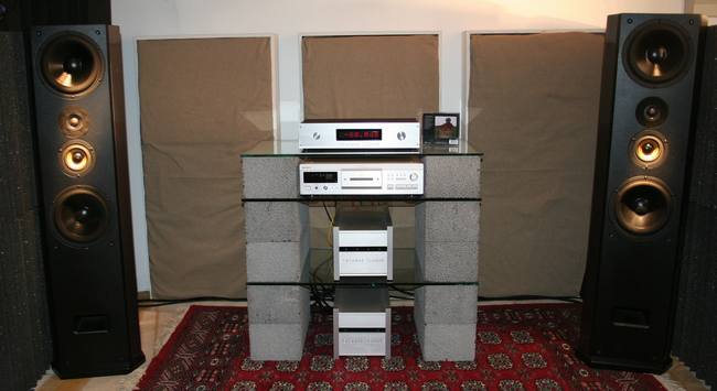
When you "convert" from passive to active, you get more electronics - a digital (or analog line level)
crossover + x number of amplifier channels. In this case, Ground DCN28 sound, which is a digital
preamplifier, digital crossover, equalizer and room optimization (electronic attenuation of room modes).
Furthermore we go from 1 pc. 2-channel power amplifier to 2 pcs. power amplifiers - 1 x 2-channel +
1 x 4-channel amplifier. So we have expanded with 4 power amplifier channels - one for each driver/ range.
Of course there will be some more cables and it may initially require that you keep cool and organized
while connecting all of the cables/wires - avoiding the burn of a treble. Here it may come in handy
with some colors. One of my old and easy mnemonic is the colors of a traffic light - red = top, yellow
= mid, green = bottom. Has been running 3-way active systems since the mid 80'ies. A problem arises
when you suddenly have to run 4-way ...
That's it - now comes the fun and easy part of the conversion to active:
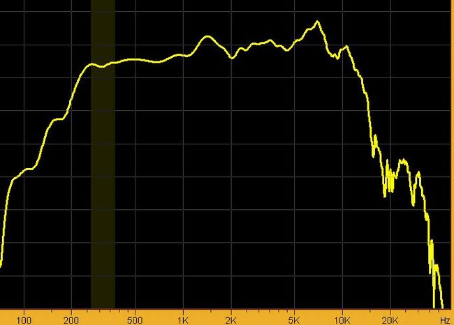
A measurement for each driver / range has to be done. I always start with the tweeter first to get a
reasonable level SPL - not too low with the risk of poor signal to noise ratio and not too high with
the risk of burning a tweeter. It is full spectrum pink noise measured with (MLS).
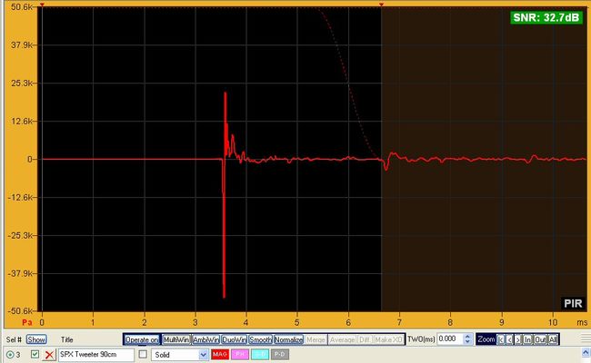
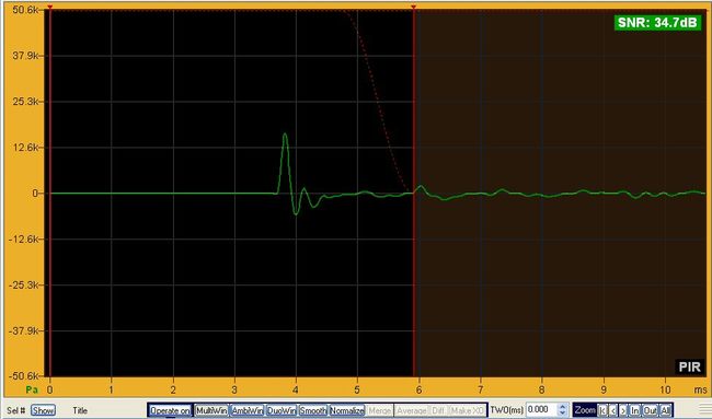
Above is the impulse for Scan Speak D2905/9700 in the SPX cabinet. As you can see, the impulse starts
negative, which indicates that I guessed wrong when I guessed which of the leaders in the twin wire was
the right + to the tweeter from the passive crossover - there was a 50% chance. Well, never mind - it can
easily be correct in the software = a single check mark in the box "Rev.Polarity".
The "gating" (MultiWindows) is set just before the first reflecting pulse (floor) and this way the effects
of measuring in a room is minimized. It is now easier to optimize the loudspeaker based on the device's
response in the enclosure.
The gated pulse gives a frequency response of the tweeter in the enclosure. The measurements are dependent
upon where you measure and has to be carefully considered. In order to optimize a multi-way dynamic speaker,
I usually measure at a distance of approx. 90cm and midway between the tweeter and midrange and "On Axis",
as this is most critical for optimization of the delay.
The response isn't smoothed and it's measured in box. The developer/designer of SPX enclosure
has decided to compensate slightly for the lack of opportunity for delay in the passive crossover by
counter sinking the tweeter more than just the flange and then fill the gap with a felt pad with a round
hole. It has almost become optimal except for the diffraction from the round felt edge ... dips at 5kHz
and 10kHz. It would have been smarter to cut the felt hole as a star or similar. Further more you can see the
edge diffraction from the enclosure at 2kHz. What can you do about these dips apart from changing the felt
hole - not really anything electronically other than a modest attenuation of the area above and below the
dips.
It would have been nicer if the tweeter was not "tried" optimized for passive filtering and thus no
dips in the frequency response then using processing in the digital domain, simply add a little delay
- often in the range of 0.1 ms.
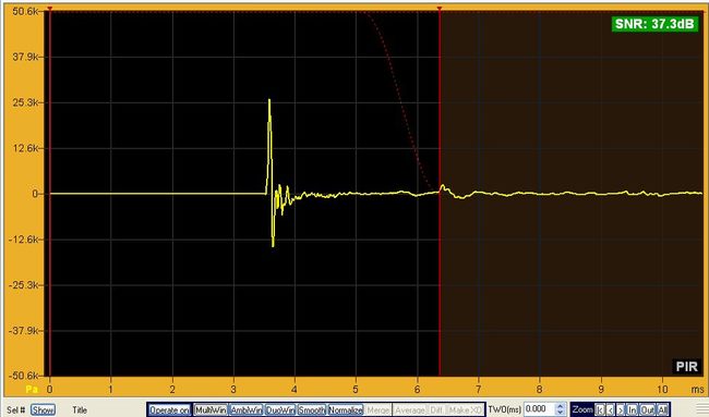
Above is the impulse of the midrange in cabinet and the impulse is correctly phased because I could see
which was + on the driver and it results in a frequency response:
The response of the midrange shows an acoustical slope of approx. 12dB / octave already at 250Hz, but no
wonder as it's a small 5" driver with very large flange - I would have liked a larger midrange like 15W
... which I personally have used with the same tweeter and resulting in much better transition. Of course
it is a nice little challenge to get an optimally frequency curve ... Has to be something like acoustic
+ electric slope for midrange and only electric slope for the bass.
The bass impulse is "luckily" correct too and it results in this frequency response:
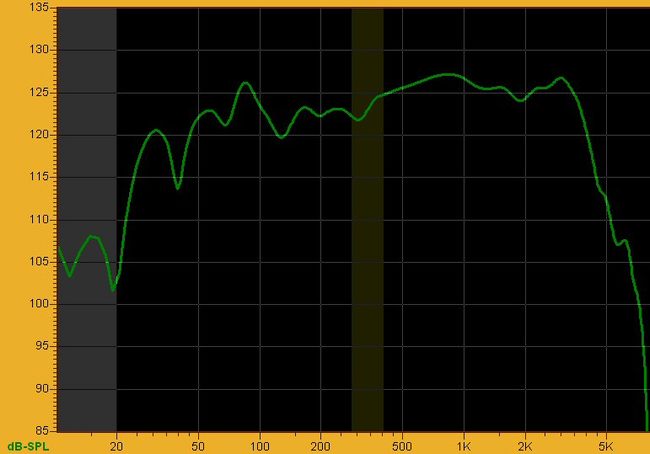
Maybe it was the peak at approx. 80Hz, that was bothering my ear ...? And you also get a glimpse of a
little lack of level in the lower bass. And remember that this is measured "in room" so frequency
response is affected by this and therefore the somewhat wavy curve (phase-outs) ... which one should
take into account when compensating (not to compensate dips).
Having some experience, one can achieve the above result in approximately a quarter of an hour in the XOverWizard II
advanced software, in which the biggest challenge was to get the transition between midrange and bass to
proceed smoothly. See individual frequency curves under the blue total - it's within reason the same dB /
octave slopes. This is the simulated curve ... And below is the measured curve after uploading the overall setup
into the DCN28 hardware:
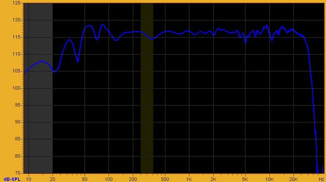
Actually quite satisfactory - even to one's ears. 
This project is meant as an appetizer for the creative man (or woman),
and even an invitation to a
tech talk at the exhibition in Copenhagen held in September 22+23 2012.

| 
 active@groundsound.com